Prior to supporting custom tool shapes, you could create the correct toolpaths by “cheating” and using one of the normal tools.
For example, to make a toolpath for a double-radius tool, you define a flat end mill with a diameter corresponding to the inner diameter (D) of the custom tool.

Left: Custom tool. Right: Defined tool used for toolpath calculation.
Next, when you select the contours, you should select the outermost contour, like on the screenshot below. This selection corresponds to the point at diameter D, and length L from the tip of the tool on the custom tool above.
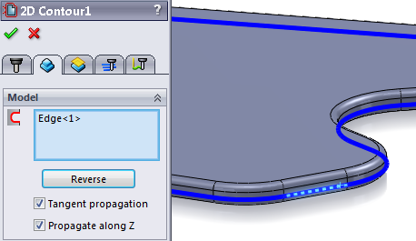
Select the contour along the outer edge
Finally, as the toolpath by default is created with the tip at the depth of the selected contour, we need to adjust the bottom height according to the custom tool dimension L. In the following example, L equals 3.0mm and so bottom should be -3.0mm from the selected contour.
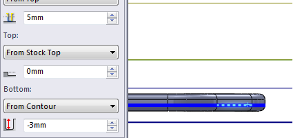
Adjust the bottom to be -L, in this example L=3.0mm
You can now simulate and post the result and it should run correctly with the custom tool. The only limitation is that the actual custom tool is not shown in simulation.
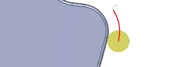
Simulating the custom tools